Location:Home > News >
FIBER OPTIC TECHNOLOGY AND ITS ROLE IN THE INFORMATION REVOL
Fortunately, a major breakthrough was achieved by Charles Kao and George Hockham at Standard Telecommunications Laboratories Ltd. (STL) (now part of Nortel) , who in 1966 pointed out that the attenuation of glass was largely caused by the presence of impurity metal ions, such as iron, copper, vanadium, and chromium, and that if a glass could be developed with attenuation of only 20 dB/km, then optical communication could become a reality. With such a fiber, 1% of the input light reaches the far end of a 1 km length of fiber. Fig.(3) shows Charles Kao at work in his laboratory at Harlow, England in 1966.

Kao and Hockham’s work spurred the efforts of others and in 1970 scientists Donald Keck, Robert Maurer, and Peter Schultz at Corning Glass achieved the attenuation figure of 20 dB/km. By 1975 this figure was down to 4 dB/km. Attenuation in state-of-the-art fibers has declined steadily since then, reaching 0.5 dB/km in 1976 and 0.2 dB/km in 1979. This last figure can be put into perspective by pointing out that for a fiber 10km long with an attenuation of 0.2 dB/km, about 63% of the light reaches the far end of the fiber. Imagine still being able to see quite clearly through a window 10 km thick! The development of fibers possessing such low attenuation has provided optical communication systems with the information carrying channel that they need. It can not be stressed too strongly how the efforts of glass scientists have made possible the information technology age.
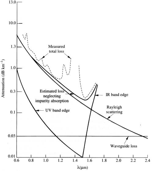
Reductions in attenuation of modern fibers have been accomplished by developing optical fiber fabrication techniques that eliminate impurities, particularly hydroxyl ions when the lowest attenuations are required. It should be acknowledged that the lowest attenuation levels have not been achieved for visible light but at two wavelengths in the near-infrared part of the spectrum, near 1.3 micrometers (m m) and 1.55 m m. Fig.(4) shows the variation of attenuation with wavelength of a typical modern fiber . The attenuation in the near-infrared is close to the minimum achievable values, which are determined by fundamental physical phenomena in the glass, which are not determined by impurities.

ABSORPTION IN OPTICAL FIBERS
Residual absorption in low loss modern optical fibers comes from several sources: residual ultraviolet absorption, residual infrared absorption, and Rayleigh scattering. Hydroxyl ions (OH-) absorb light near 2.73 m m, with weaker absorptions at 1.39, 0.95 and 0.72 m m. The hydroxyl content must be kept below 1 part per million (ppm) in order that the attenuation at 0.9 m m be less than 1 dB/km. Even if the water content of the fiber is minimized, residual absorption remains from the infrared absorption of the fundamental vibrations of the bonds that make up the glass, which occur at 7.3 m m for boron-oxygen bonds, 8.0 m m for phosphorous-oxygen bonds, 9.0 m m for silicon-oxygen bonds, and 11.0 m m for germanium-oxygen bonds. These absorptions influence the attenuation of the fiber even at shorter wavelengths. The remaining significant, unavoidable attenuation mechanism in the fiber is Rayleigh scattering -- the natural tendency for any atom or module to reradiate in all directions a part of the electromagnetic radiation incident on it. The magnitude of this scattering increases dramatically at shorter wavelengths, and is enhanced by the random structural character of glass. Indeed it is this phenomenon that causes the sky to appear blue: the shorter wavelengths in sunlight (the blue light) scatter more strongly than other colors. Microscopic variations in material density in a glass fiber lead to concomitant variations in refractive index that enhance Rayleigh scattering. This loss can be minimized by drawing the fiber during production so as to minimize compositional variations.
WHY ARE OPTICAL FIBERS SO GOOD FOR COMMUNICATIONS?
The information-carrying capacity of an optical fiber is far greater than it is for its competitors: wires, coaxial cables, and microwave links. In addition, optical fibers are inexpensive to produce, do not conduct electricity (which makes them immune to disturbance by lightning storms, and other electromagnetic signals – except nuclear radiation), do not corrode, and are of small size. The primary reason that optical fibers have very much larger information-carrying capacity than other media, is that they carry light: this might seem a trivially obvious observation but it has fundamental significance. The frequency of the light beams that travel along optical fibers is in the vicinity of two hundred trillion cycles per second (Hz). Compare this with the frequency of the latest generation of personal communication service (PCS) cellular wireless systems – approximately two billion cycles per second (2 GHz). Consider the frequencies that must be transmitted for voice communications, which cover the range (bandwidth) from about 50Hz to 20,000Hz (20kHz). Indeed, since there is very little need to include the high frequencies for understandable voice communications, the actual bandwidth needed is really only about 4 kHz. It is possible, in principle, to carry about 50 billion voice conversations on a single laser beam in an optical fiber. This capacity results from the very simple calculation:
2.1014Hz/4.103Hz=50.109.
The entire population of the Earth could be on the phone on a single fiber at the same time! The corresponding capacity of a PCS link is about 500,000 simultaneous voice channels. In practice, it has not proven possible to achieve these maximum capacities, although in current links the optical fiber wins by a huge margin. The domination of optical fiber as a means for carrying information is apparent when we note that such fibers are being manufactured worldwide at a rate of 2000 miles per hour! Whether an optical or microwave link has the ability to use its full capacity depends on the way in which the information is encoded, and how different messages are mixed together (multiplexed) without them all getting mixed up. To understand in more detail how this is done, we must digress and discuss the nature of digital representations of information and how this influences the way in which information, whether this be voice, video, or computer data, is encoded and transmitted.
DIGITAL ENCODING OF INFORMATION
Many years ago all information was transferred in an analog format, which meant that the message was transmitted essentially as an exact copy of the original. The best example comes from early telephones. When a person spoke on the telephone, a microphone in the handset converted the sound waves from the voice into an electrical signal (varying electrical voltage or current), which mimicked the variations in air pressure produced by the persons’s voice. This analog signal was sent along electrical wires to its destination, where the electrical signal drove a small loudspeaker and recreated the sound of the caller’s voice. The principal problem in this scheme was that the electrical signal became distorted in its passage from caller to listener. And, in addition, the electrical signal had to be amplified along its way to counteract the loss of energy that naturally occurs to all electrical signals passing along wires. Amplification itself adds some distortion, as well as adding noise, a randomly fluctuating background electrical disturbance produced in all electronic systems as a fundamental natural phenomenon. All these problems can be circumvented if the transmitted electrical signals are digitized – represented in a binary code.
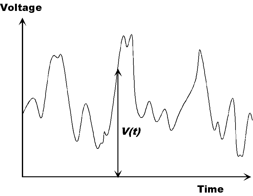
Consider a short duration record of a voice. This could be a time-varying voltage of the form shown schematically in Fig.(5). At each instant of time, the magnitude of the voltage has a specific value, which can be represented as V(t). This voltage can on an arbitrary scale be represented by a normal decimal number, say N(t). If we convert the number N into the binary system then it will be written as a series of "ones" and "zeros," called bits. For example, if N=59, then we can write:
59=32+16+8+2+1,
which can be seen to be
59=25+24+23+21+20.
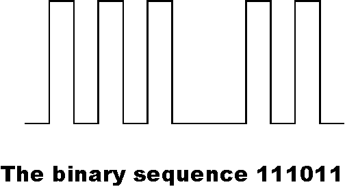
So, the binary representation of 59 is 111011. Note that the "ones" show up where the appropriate power of 2 is needed to build up the number. This binary number could be represented by the binary voltage signal shown in Fig.(6).
If we take the values of V(t) at equally spaced time intervals, and represent each value of the voltage by its binary voltage signal, then we can create a continuous binary representation of the original analog signal. This is called analog to digital conversion (A/D). To make this binary representation an accurate record of the original signal there must be sufficient samples of the analog voltage taken, and each must be encoded by sufficient binary bits. The number of binary bits depends on how faithfully the instantaneous amplitude of the signal must be digitized. If 16 bits are used, this means that a scale of 216, namely 65,536, different voltage levels are used to characterize the range of values that can be taken by the varying voltage V(t). In practice, this means that the loudest sound signal that could be faithfully reproduced would be equivalent to 65,536, and the quietest would correspond to 1. In addition, samples should be taken at twice the maximum frequency it is desired to include in the representation of the signal. So, for example, speech digitized at 8 bits (28=256) to include frequencies up to 4kHz would produce a bit rate of 64,000 bits per second (b/s). (64,000=8X4,000X2.) Music digitized at 16 bits to include frequencies up to 20kHz would need a bit rate of 640,000 bits per second.
Once information has been digitized it can be transmitted from the source of the message (the sender) to its destination (the receiver) without as much concern about distortion and added noise. At the receiver, unless severe distortion has occurred during transmission, it is easy to re-create a perfect representation of the transmitted binary signal, since for each time interval a simple decision must be made – is this a "one" or a "zero".
It is worthwhile considering for a moment the number of bits of digital data associated with the transmission (or storage) of various kinds of information. A compact disc (CD) with one hour of music typically contains about 680 Megabits (Mbs) of digital data . A computer CD ROM contains a similar quantity of data. Video requires somewhat larger numbers of bits per hour, because both the picture and accompanying sound must be stored. However, clever techniques for compressing the imagery can reduce the quantity. The latest generation of digital video discs carry 4.7 Gb of data per side. Double sided, double layered DVDs can carry four times as much data – more than 17 Gb of data. A single-sided, single-layered disc, stores 133 minutes of film (with accompanying audio), so the average rate of data transfer during viewing is about 0.6 Mb /s. For real time video transmissions the rate of data transfer required is higher, in the range from 3 to 5 Mb/s. To download a 2 hour long DVD movie over a link within 10 seconds requires a data transfer rate of around 0.5 Gb/s. You can’t get such data rates through your phone line! However, if optical fiber is installed directly to your home this changes your access to information directly. Fiber-to-the-home, as it is called, is not yet here because of the cost involved – estimated to be around $1,000 per household. The telephone and cable companies have not identified a current demand for digital communication services that needs the data rates provided in this way. The technology to do it is here, but not the will for the capital investment required.
In a digital link along an optical fiber the simplest way to represent the data is to switch a laser between two intensity values, the high value representing a "one", and the low value a "zero." In other words a series of pulses of light are transmitted, whose occurrence in time represents the times of "ones" with the gaps in between representing the "zeros." The maximum rate at which such pulses can be transmitted, received, and processed is not at present limited so much by properties of the fiber, as it is by the speed of the conventional electronics that must switch the laser on and off, detect the received light pulses and, if required reconvert them back from binary to analog format (digital-to-analog conversion – D/A). At present, the maximum pulse rate that can be handled in practical systems is about 10 billion bits per second (10Gb/s). However, recent developments have made possible a massive increase in this data rate. These developments include the development of the Erbium Doped Fiber Amplifier (EDFA), and wavelength division multiplexing (WDM). However, before discussing these we must digress to discuss the use of repeaters and the phenomenon of dispersion.
REPEATERS AND DISPERSION
As was mentioned earlier, even though modern optical fibers are extremely transparent, attenuation of the intensity of the light traveling along the fiber still occurs, and over long distances the light signal must be boosted back to a larger value. This process was traditionally carried out with a repeater. This is a device incorporating a light detector, processing electronics, and a new laser. An incoming stream of optical pulses, corresponding to the transmitted information in binary code, is detected and becomes an equivalent stream of electrical pulses. These electrical pulses are amplified, reshaped electronically to restore their original shape, and are then used to drive the new laser to re-transmit the information along the next stretch of fiber. In this way, a stream of optical pulses can be transmitted over great distances, such as under the Atlantic Ocean, by spacing a series of repeaters along the fiber cable. Typically repeaters are spaced every 45-70 km. Consequently, a long fiber cable must incorporate conventional electrical wires to provide the power to drive the repeaters.
One great advantage of a system with repeaters is that it has the ability to restore their original shape to propagating light pulses. There is a natural tendency for an optical pulse traveling along an optical fiber to change its shape. This results from a phenomenon called dispersion. Dispersion is the change in the velocity of light with the wavelength of the light. Usually, shorter wavelengths travel more slowly than longer wavelengths, so for example in a very long fiber a red pulse of light will get to the far end of the fiber more quickly than a blue pulse. A short optical pulse always contains a range of wavelengths. Although this might not be obvious, an analogy can be made. A pure musical tone, in its ideal form gives a sound wave that undulates at a distinct frequency, for example middle C is 523.25 Hz. A pulse of sound, which might be made for example by the crack of a whip has no such purity and actually contains a range of sound wave frequencies, called the spectrum of the pulse. A light pulse is no different. The effect of dispersion is to make a narrow optical pulse become broader the farther along a fiber it travels. If this phenomenon is not dealt with, it imposes severe limits on the rate at which information can be transmitted over long distances.
Suppose that it is desired to transmit binary encoded data at a rate of 1 Gb/s (one billion bits per second). It should be fairly obvious that if these optical pulses are to remain distinct they must be separated from each other in time by about one half of a billionth of a second -- 0.5 nanoseconds (ns). So the pulses should not be longer than about 0.5ns. If the pulses were able to spread to a width of 1ns they would overlap, and their distinct identity in the pulses stream would be lost. If these pulses are detected at a repeater before they have spread too much, their original 0.5ns width can be restored, and the pulses will not continue to broaden in traveling great distance along a fiber. This is the clear advantage of a fiber system with repeaters. However, there is a disadvantage to repeaters: they can not distinguish pulses at one wavelength from pulses at another wavelength. This prevents an increase in the information carrying capacity of the fiber by simultaneously transmitting different data streams, each corresponding to a train of light pulses from a laser operating at a different wavelength. For example, if a red and blue laser simultaneously carry two messages along a fiber, at the far end the two messages can be separated and read simply by using a blue filter to collect the blue light and a red filter to collect the red light. This scheme is wavelength division multiplexing. Unfortunately, if a repeater is included, it must be of sufficient complexity to separate the two wavelengths, process the two electrical signals independently, and then drive two new lasers to re-transmit the messages. This complexity is avoided by the use of erbium doped fiber amplifiers.
ERBIUM DOPED FIBER AMPLIFIERS (EDFAs)
In 1987 David Payne and his co-workers at the University of Southampton in England reported the operation of the first practical optical amplifier suitable for lightwave communication systems. The EDFA uses an optical fiber with the rare- earth ion erbium added as an impurity. If optical energy is fed into a section of such a fiber, which uses an auxiliary laser (called the pump laser), than a stream of optical pulses will pass through the amplifier and each pulse in the stream will be amplified (boosted in size). This amplification process occurs for a relatively broad wavelength range near 1.55 m m so many different messages being carried on laser beams of different wavelengths can be simultaneously amplified . Current developments in this scheme use up to 40 different laser wavelengths (which have different frequencies) spaced in frequency by 100 Ghz. Each wavelength can carry data at 10Gb/s so the total capacity of the fiber has been increased to 400 Gb/s. Very soon it appears likely that this will be increased to 80 channels.
The astute reader might notice that this EDFA scheme only amplifies the light pulses, but does not deal with the problems of pulse width spreading that result from dispersion. At first glance it might appear that if pulses travel great distances and pass through several EDFAs that they will arrive at their destination with a reasonable amplitude, but that there will have been cumulative pulse broadening along the entire length of fiber. This problem is dealt with by a process called dispersion management. By including additional dispersive elements in the optical chain that runs from transmitter to receiver, it is possible to play off positive and negative dispersion effects against each other and prevent overall pulse spreading over great distances.
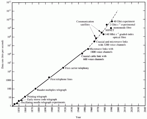
The development of low loss, low overall dispersion, single-mode fibers, with EDFAs to allow long distance transmission, may serve to satisfy the world's insatiable appetite for ever-increasing data rates. This is graphically illustrated by Fig.(7), which shows how the data rates of communication channels have grown since the early days of the telegraph. This figure was drawn in 1995, and is already out of date.
The projected capacity of a single fiber communication channel of 1012 bits per second (1 Terabit/s), which the figure above suggests will happen around 2,005, is already here. Worldwide Internet traffic is about 1 Terabit per second, and could therefore, in principle, be carried on a single optical fiber. A typical optical fiber cable containing 8 distinct fibers will carry 8 Terabits per second, or 20 million Terabits per month. The current level of traffic on the Internet in North America is about 3000 terabits per month. The information carrying capacity of optical fiber is actually increasing much faster than linearly on an annual basis. The capacity of optical fibers has increased 100 times in the last ten years while the speed of integrated circuits (which are found in all modern electronics such as computers, compact disc players, and cellular telephones) has increased by only a factor of 60 over the same period.
OPTICAL COMMUNICATION NETWORKS
Fiber optic links have been extensively installed worldwide. Most long distance (trunk) lines use single-mode fiber and increasingly high data rates. A current standard is the 2.488 Gbit/s maximum data rate of SONET (synchronous optical network). A typical SONET optical fiber link will carry 32,000 simultaneous two-way voice or data channels on one pair of fibers. SONET is designed to interface with and replace existing communication networks that operate at various data rates. The lowest level SONET signal is called the Synchronous Transport Signal Level 1 (STS-1), which has a data rate of 51.84 Mbit/s. Higher data rates are achieved by multiplexing N of these data streams up to a maximum of N=48. SONET uses single-mode fiber and different types of light source depending on the ranges involved. Short reach links (up to 2 km) use light emitting diodes (LEDs) or multimode lasers operating at 1.31 m m; intermediate reach links (up to 15 km) use 50 m W single- or multi-mode laser transmitters operating at 1.31 m m or 1.55 m m. Long reach links (up to 40 km) use 500 m W laser transmitters at 1.31 m m or 1.55 m m. For local area networks (LANs) that use LED sources and multimode fiber the Ethernet standard (3 Mbit/s) is widely used, although when higher data rates are required the Fiber Distributed Data Interface (FDDI) standard is common. This is a 100 Mbit/s channel that through technological developments allows interfacing of a FDDI optical network with twisted-pair cable for final connection to transmit/receive users of the network. In these hybrid systems the electrical connection is typically only the last 100 m or so to the user from the fiber-based part of the system. The standard for interfacing FDDI networks via twisted-pair cables over these typically 100 m connections is called the Twisted-Pair Distributed Data Interface (TPDDI). In modern optical networks GaAlAs/GaAs lasers are being superseded by 1.3 m m and 1.55 m m InGaAsP-based lasers for connections in excess of a few kilometers.
TRANS-OCEAN OPTICAL FIBER CABLES
The longest fiber links are those that span the world's oceans, including several across the Atlantic from North America to Europe and several from the United States to Japan. Many additional long distance fiber links exist: by 1995 there were nine across the Atlantic, four from the United States to Japan, one from Japan to China, with additional links for Australia, Korea, India, South and Central America, South Africa, and New Zealand . The transatlantic cable laid in 1988 (TAT-8) contains eight fibers and can carry 40,000 telephone calls at one time: each pair of fibers carries 560Mb/s. The next generation of cables (TAT-9 and TAT-10), which came into service in 1992, carry double this number of calls. TAT-11 has the same capacity as TAT-9 and TAT-10. It stretches 7,162 km from Manahawkin, New Jersey to a location 600 miles from both Ireland and France where it splits and continues to Swansea, in the U,K, and St. Hilaire in France.
The newest trans-Atlantic cable TAT-12/13 is the first such cable to use EDFAs rather than the old-style repeaters. This cable forms a ring of undersea segments connecting together cable stations in Green Hill, Rhode Island; Lands End, England; Penmarch, France; and Shirley, New York. It is 12,400 km long. The segment from Green Hill to Lands End is 5,913 km long. One segment of the cable 3,759 km long was installed by STC Submarine Systems. There are 133 EDFAs spaced 45 km on the remaining segment 2,154 km long installed by AT&T Submarine Systems. Each of the cable segments contains two fiber pairs, one used for regular service, and the other for emergency restoration service. The capacity of each fiber pair is 2.5Gb/s, so the overall capacity of the system is 10 Gb/s. The two main cables are laid several hundreds of kilometers apart on the ocean floor, and are routed to avoid hazardous areas, surface and deep-sea current, seismic activity, military activity, and fishing.
All these fiber cables are heavily armored against shark bites and in the shallow part of the ocean are buried under the ocean floor to prevent their being snagged by fishing boats. Repeaters (old-style or EDFA) are placed every 45--75 km. The old-style repeaters have built-in redundancy, incorporating extra detectors and lasers so that if one device fails the channel remains functional. It is prohibitively expensive to dredge up cables to modify or repair repeaters or erbium doped fiber amplifiers. Fortunately the reliability of TAT-12/13 is projected to be such that only one undersea repair per 25 years should be needed.
Tyco Submarine Systems (TSSL) announced that a doubling of capacity of TAT-12/13 would be achieved by July 1998 by upgrading it to 2-wavelength WDM operation. An extension to a third wavelength, which would increase capacity to 30 Gb/s, is being considered for July, 1999.
In September, 1998, more than 50 communication carriers signed an agreement to construct TAT-14, the next Trans-Atlantic link, at a cost of $1.5 billion. This cable will use WDM with 8 wavelengths per fiber pair, and has 64 times the capacity of TAT-12/13. TAT-14 will use 4 fiber cable pairs. Each fiber pair has a capacity of 160 Gb/s, so the total system capacity is 640 Gb/s. It could carry 7.7 million telephone calls at the same time. About 80% of the cable capacity will be allocated to Internet and multimedia traffic. If one considers that the lowest typical price for a Trans-Atlantic telephone call is 10 cents per minute, and probably averages in reality about $1.00 per minute, then the cable pays for its installation costs in about 24 hours!. Because carriers can charge more for high speed connections the system (if fully utilized) probably makes back its installation costs in about 12 hours!
Gemini is another Trans-Atlantic fiber cable pair with a capacity of 60 Gb/s that stretches betweem England (Porthcurno and Oxwich Bay) and New York City (Manasquan, NJ and Charlestown, RI). The two cables are laid 740 km apart. This cable was a joint venture of Cable&Wireless and WorldCom.

OPTICAL FIBER NETWORK ARCHITECTURES
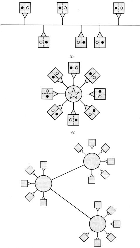
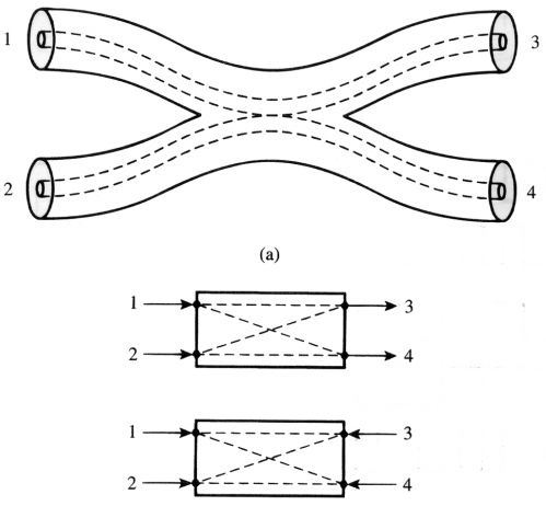
Fig.(8) shows three popular topologies of optical networks. In these arrangements of transmitters and receivers, each transmitter/receiver pair on the network, which is called a node or subscriber can communicate with every other. The construction of such networks relies on the use of various passive optical components for their implementation. The most important of these is the fiber coupler, one form of which is shown schematically in Fig.(9), that either splits or combines optical signals. This is a four-port device. In the simplest sense such a device is fabricated by fusing together two single mode fibers so that their cores come close together, allowing light to leak from one core to the other. Depending on the splitting ratio between the ports the device can be described as either a tap or splitter.
For example, in Fig.(9), if light enters port 1 it is split on output between ports 3 and 4. Port 2 functions in the same way, although usually one of ports 1 or 2 will be unused if it is desired to act as a Y (or T) coupler. If the intensities leaving ports 3 and 4, respectively, on injection of light at port 1 are equal the coupler is referred to as a 3 dB coupler or splitter, on the other hand if 99% of the input power passes from port 1 to port 3, with only 1% leaving at port 4 the device is described as a 20 dB coupler or tap.

LINE-OF-SIGHT OPTICAL LINKS
Line-of-sight optical links, which involve the free space propagation of the encoded light signal from source to receiver, have only limited, short range application in ground-based situations. Turbulence, scattering, and absorption by the atmosphere introduce amplitude and phase noise into the transmitted signal and cause significant signal amplitude decay over moderate distances. However, ground-to-satellite, satellite-to-satellite, and deep-space communication links represent important application areas for line-of-sight optical communications. When the communication channel must be guaranteed, as in a commercial satellite ® ground link, microwaves are generally preferred because their long wavelengths can penetrate clouds. An optical downlink, even to a generally cloudless location such as the mountains of Arizona or Hawaii, or the deserts of Australia cannot provide 100% reliable visibility conditions. Nonetheless, there are specialized applications of such links: a blue-green laser can be transmitted from an aircraft or satellite and provide a secure high data rate communication channel to a submerged submarine. Optical links between satellites in near-earth orbit will be of increasing importance in the future for global communications. A series of satellites in synchronous earth orbit (at a height of 38,600 km) can provide global communications coverage and can relay information from closer-in satellites used for earth observation. The NASA Earth Observing System (EOS) program uses such satellites for continuous, long term monitoring of earth resources, climatic conditions, and atmospheric composition. The primary advantage of optical links for space communications is that a much more directional beam can be sent from source to receiver, so transmitter requirements for long distance transmission are reduced. The most challenging application of such a link is in deep-space communications. In explorations of the outer planets in programs such as Pioneer and Voyager, data is relayed to and from the space craft with microwaves. Because the transmission distances are so long, high transmitter powers are required, which presents a problem for the space craft end of the system, which must rely on solar power. If a short wavelength laser is used as the transmitter on the spacecraft, a substantial reduction in transmitted power is possible because a more directional beam is possible.
Get in Touch
+86-21-3996-3837
alex@changguangchina.com
+86-15216725374


