Location:Home > Knowledge >
Basics of fiber optic cable
Standards
Most of what we call standards are voluntary standards, created by industry groups to insure product compatibility.They are not "codes" or actual laws that you must follow to be in compliance with local ordinances.
Standards like EIA/TIA 568B ( from the Electronic Industries Alliance/ Telecommunications Industry Association)
which covers all of the things you need to know to install a standard premises cabling network are good
guidelines for designs, but just guidelines - they are not mandatory. Standards for fiber optic components
and testing have been set by several groups, but most in the US follow the EIA/TIA developed
FOTP's (fiber optic test procedures) for testing. Some of the EIA procedures are also called
OFSTP (optical fiber system test procedures) like OFSTP-14 for the installed cable plant.
Standards for optical power measurements are set by NIST (the US National Institute
of Standards and Technology) The only common mandatory standard is the NEC 770
(National Electrical Code). The NEC specifies fire prevention standards for fiber
optic cables. If a cable doesn't have a NEC rating - don't install it - it won't pass inspection!
A complete listing of the EIA/TIA standards is on the Information on the EIA/TIA standards
can be found on the website of most of he suppliers of structured cabling hardware.
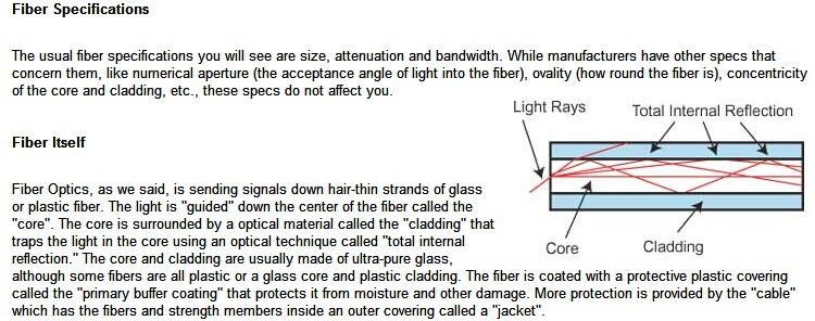
Multimode & Singlemode Fibers
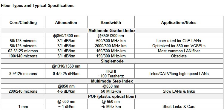
Multimode & Singlemode fiber are the two types of fiber in common use. Both fibers are 125 micronsin outside diameter - a micron is one onemillionth of a meter and 125 microns is 0.005 inches- a bit
larger than the typical human hair. Multimode fiber has light traveling in the core in many rays,
called modes. It has a bigger core (almost always 62.5 microns, but sometimes 50 microns )
and is used with LED sources at wavelengths of 850 and 1300 nm (see below!) for slower local
area networks (LANs) and lasers at 850 and 1310 nm for networks running at gigabits per second
or more. Singlemode fiber has a much smaller core, only about 9 microns, so that the light travels
in only one ray. It is used for telephony and CATV with laser sources at 1300 and 1550 nm.
Plastic Optical Fiber (POF) is large core ( about 1mm) fiber that can only be used for short,
low speed networks.
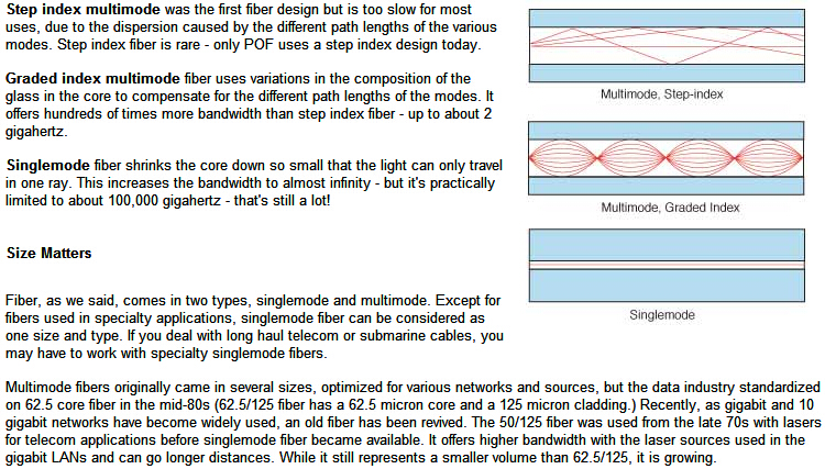
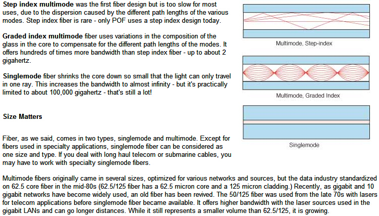
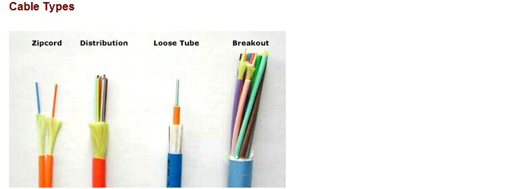
Simplex and Zip Cord: Simplex cables are one fiber, tight buffered (coated with a 900 micron buffer
over the primary buffer coating) with Kevlar (aramid fiber) strength members and jacketed for indoor use.
The jacket is usually 3mm (1/8 in.) diameter. Zipcord is simply two of these joined with a thin web.
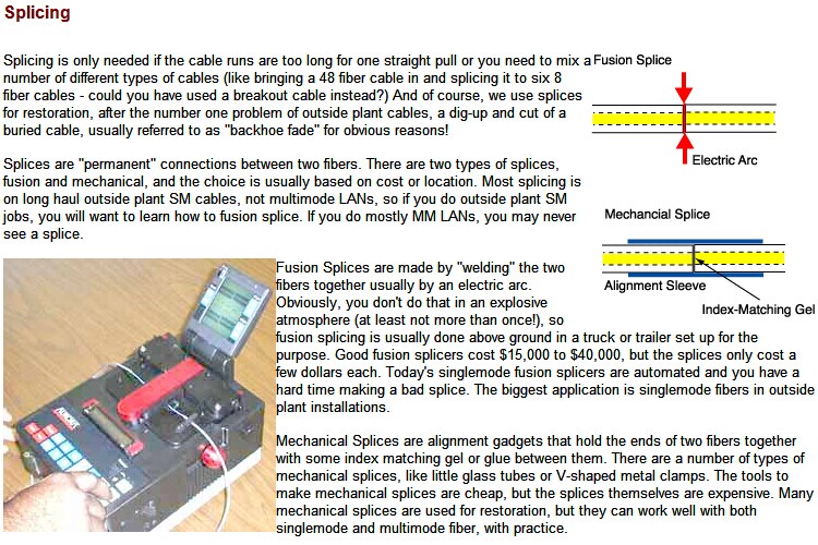
It's used mostly for patch cord and backplane applications, but zipcord can also
be used for desktop connections.
Distribution Cables: They contain several tightbuffered fibers bundled under the same jacket
with Kevlar strength members and sometimes fiberglass rod reinforcement to stiffen the
cable and prevent kinking. These cables are small in size, and used for short, dry conduit runs,
riser and plenum applications. The fibers are double buffered and can be directly terminated,
but because their fibers are not individually reinforced,
these cables need to be broken out with a "breakout box" or terminated
inside a patch panel or junction box.
Breakout Cables: They are made of several simplex cables bundled together.
This is a strong, rugged design, but is larger and more expensive than the distribution cables.
It is suitable for conduit runs, riser and plenum applications. Because each fiber is
individually reinforced, this design allows for quick termination to connectors and does
not require patch panels or boxes. Breakout cable can be more economic where fiber count isn't
too large and distances too long, because is requires so much less labor to terminate.
Loose Tube Cables: These cables are composed of several fibers together inside a
small plastic tube, which are in turn wound around a central strength member and
jacketed, providing a small, high fiber count cable. This type of cable is ideal for outside
plant trunking applications, as it can be made with the loose tubes filled with gel
or water absorbent powder to prevent harm to the fibers from water. It can be used in
conduits, strung overhead or buried directly into the ground. Since the fibers have only a
thin buffer coating, they must be carefully handled and protected to prevent damage.
Ribbon Cable: This cable offers the highest packing density, since all the fibers are laid
out in rows, typically of 12 fibers, and laid on top of each other. This way 144 fibers
only has a cross section of about 1/4 inch or 6 mm! Some cable designs use a
"slotted core" with up to 6 of these 144 fiber ribbon assemblies for 864 fibers in
one cable! Since it's outside plant cable, it's gel-filled for water blocking.
Armored Cable: Cable installed by direct burial in areas where rodents are a
problem usually have metal armoring between two jackets to prevent rodent
penetration. This means the cable is conductive, so it must be grounded properly.
Aerial Cable: Aerial cables are for outside installation on poles. They can be
lashed to a messenger or another cable (common in CATV) or
have metal or aramid strength members to make them self supporting.
Even more types are available: every manufacturer has it's own favorites,
so it's a good idea to get literature from as many cable makers as possible.
And check out the little guys; often they can save you a bundle by making special
cable just for you, even in relative small quantities.
Why Use Fiber?
If fiber is more expensive, why have all the telephone networks been converted to fiber? And why are all the CATV systems converting to fiber too?
Are their networks that different? Is there something they know we don't? Telcos use fiber to connect all their central offices and long distance
switches because it has thousands of times the bandwidth of copper wire and can carry signals hundreds of times further before needing a repeater.
The CATV companies use fiber because it give them greater reliability and the opportunity to offer new services, like phone service and Internet connections.
Both telcos and CATV operators use fiber for economic reasons, but their cost justification requires adopting new network architectures to take advantage
of fiber's strengths. A properly designed premises cabling network can also be less expensive when done in fiber instead of copper. There are several good
examples of fiber being less expensive, so lets examine them.
OTDR Testing
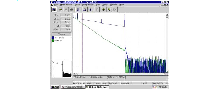
As we mentioned earlier, OTDRs are always used on OSP cables to verify the loss of each splice.
But they are also used as troubleshooting tools. Let's look at how an OTDR works and see how it
can help testing and troubleshooting.
How OTDRs Work
Unlike sources and power meters which measure the loss of the fiber optic cable plant directly,
the OTDR works indirectly. The source and meter duplicate the transmitter and receiver of
the fiber optic transmission link, so the measurement correlates well with actual system loss.
The OTDR, however, uses backscattered light of the fiber to imply loss. The OTDR works
like RADAR, sending a high power laser light pulse down the fiber and looking for return
signals from backscattered light in the fiber itself or reflected light from
connector or splice interfaces.
At any point in time, the light the OTDR sees is the light scattered from the pulse passing
through a region of the fiber. Only a small amount of light is scattered back toward the
OTDR, but with sensitive receivers and signal averaging, it is possible to make
measurements over relatively long distances. Since it is possible to calibrate
the speed of the pulse as it passes down the fiber, the OTDR can measure time,
calculate the pulse position in the fiber and correlate what it sees in
backscattered light with an actual location in the fiber. Thus it can create
a display of the amount of backscattered light at any point in the fiber.
Since the pulse is attenuated in the fiber as it passes along the fiber and suffers
loss in connectors and splices, the amount of power in the test pulse decreases as
it passes along the fiber in the cable plant under test. Thus the portion of the light
being backscattered will be reduced accordingly, producing a picture of the
actual loss occurring in the fiber. Some calculations are necessary to
convert this information into a display, since the process occurs twice,
once going out from the OTDR and once on the return path from the scattering at the test pulse.
Get in Touch
+86-21-3996-3837
alex@changguangchina.com
+86-15216725374


